How to Draw Truss in Autocad
Subjects Covered
- Refined Analysis
- 3D Frame
- Setting Out Objects - Arcs
- Construction Lines
- 2D Sub models
- Drawing 2D Beam Members
- Copying Sub Models
- 3D Sub Models
- Drawing 3D Beam Members
- Filtering
- Importing sections
- Parametric Shapes
- Structure Plots
- Data Summary
Outline
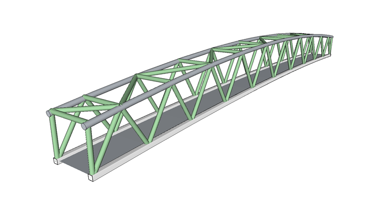
This model is of a 55m span steel truss footbridge, curved in elevation, constructed with square hollow sections for the bottom boom members and circular hollow sections for the top boom and bracing. The deck spans between the two bottom boom members and is braced diagonally with angles.
Plan of Top Boom and Bracing

Plan of Bottom Boom, Deck Members and Deck Bracing

The top boom is a 406x16 Circular Hollow section.
The bottom boom is 400x400x20 Square Hollow section.
All other members except the deck members and deck bracing are 324x12 Circular Hollow section.
The deck is constructed from 6mm thick steel plate, transversely stiffened with inverted "T" sections welded to the underside of the plate. The "T" sections are 400mm deep with a 100mm wide flange and is 10mm thick throughout. They are spaced at 500mm centres. Each transverse member in the bottom will be as shown below.

The deck is braced diagonally as shown in the plan with 75x75x12 steel angle.
The material used throughout is structural steel with an elastic modulus of 210kN/mm², a shear modulus of 81kN/mm² and a weight density of 77kN/m³. (Note that the 75x75x12 angle is to have a density of 78kN/m³).
Procedure
- Start the program and create a new project using the menu item File | New | Create from Template... and select "EU Project" from the My Templates list.
- Use the menu item Data | Structure Type | Refined Analysis to specify a refined analysis rather than a line beam.
- Using the File | Titles menu option set the Project title to "3D Truss Footbridge" with a sub title of "Example 6.3".
- Also set the Job Number: to "6.3" and put your initials in the Calculations by: field.
-
Close the form with ✓ OK.
Structure Geometry
The structure will be built up using four separate sub models: One for each truss, one for the top boom connecting members and another for the deck and bracing.
The geometry of the first truss is defined by creating two curved arcs along the lines of the top and bottom boom and then placing vertical construction lines at the location of each of the truss connections. Members can then be drawn on the graphics screen by snapping to the intersection points.
The first truss can be copied to form the second truss and then connecting members can be drawn between them.
-
To start, add a new 2D sub model to the Structure Definition navigation window, as described in example 6.2, with its plane in the XZ plane.
-
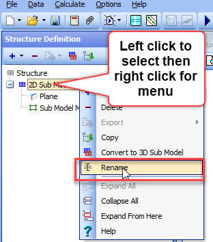
Rename the sub-model to "Truss 1" by clicking on it in the navigation window first with the left mouse button then with the right and choosing the Rename option which allows text to be entered in the Enter new name: field.

-
With the new sub model highlighted add a Setting Out Object by using the
 button and selecting the appropriate option.
 -
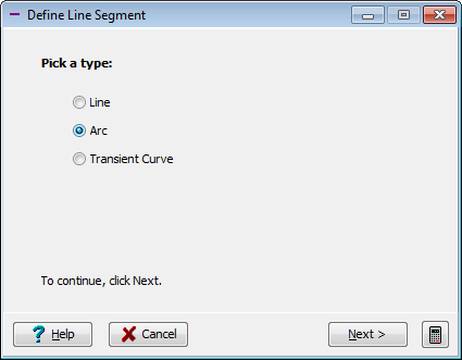
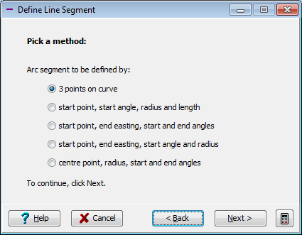
Click on the small "+" at the bottom of the Define Setting Out Object form to add a line segment. Choose Arc from the Pick a type: options and click on the Next > button.
-
The method we will choose to define the curve of the bottom boom is 3 points on curve – click on the Next > button.
-
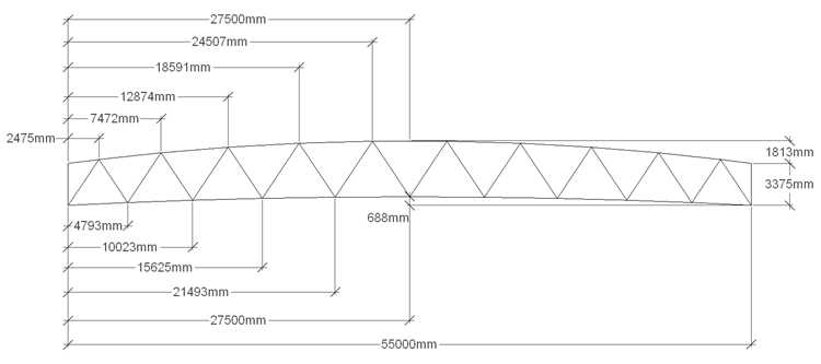
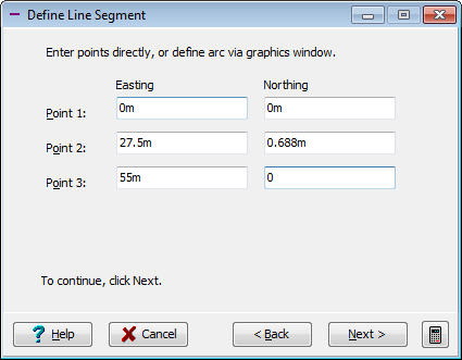
Enter the three coordinates as (0.0, 0.0) (27.5, 0.688) (55.0, 0.0) and then click on the Next > button.
-
If the curve appears correct close the wizard with the ✓ OK button otherwise use the < Back button to re-enter incorrect data.
-
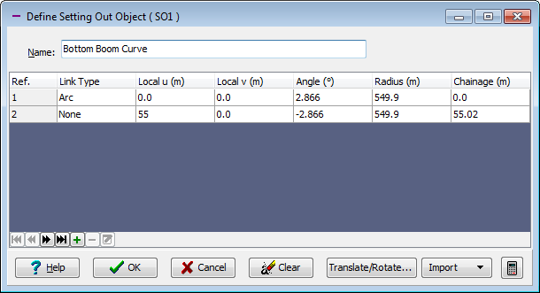
Change the Name: of the setting out object to "Bottom Boom Curve" before closing the form with the ✓ OK button.
-
Repeat steps 8 to 13 to create a second setting out object but use coordinates (0.0, 3.375) (27.5, 5.188) (55.0, 3.375) and a Name: of "Top Boom Curve."
- Add a third setting out line 3 vertically at the left end by repeating 3 to 9 but selecting line rather than an arc and choosing start and end points.
- Use coordinates (0.0, 0.0) and (0.0, 6.0), and set the Name: to "Vertical at x=0".
- Create a series of vertical lines that will intersect with the top and bottom booms offset parallel to SO3 with offsets as shown in the elevation drawing above (see the introduction to Part 6.3 of this manual).
-
Use
and select Construction lines from the list. The first offset is at 2.475m. The bottom half of the table is shown below.
-
There are 20 lines in total. The lines are added by selecting the Line Type +Offset parallel to SOL on the left of the form.
-
Select "S03" in the SOL Ref. and enter the offset accordingly. Once all lines have been created close the form with the ✓ OK button.
-
We will now connect the intersection points of these lines to create the beam members of the truss. This is done by opening the Define Sub Model Members form by clicking on the Sub Model Members item in the navigation tree.
- Select the draw mode in the graphics toolbar to multiple members
 and then set the snap mode to "Intersection". Now draw the first member of the bottom boom by clicking close to the first intersection point from the left then the third point.
 - The remaining members of the bottom boom can be created by continuing the clicking on intersection points five, seven ...etc until the last point is clicked then the "Esc" key on the keyboard will stop the selection. Any members drawn incorrectly can be deleted, by highlighting them in the table and clicking on the small "-" button at the bottom of the table, and then drawn again correctly.
- This can be repeated for the top boom except the intersection numbers will be 1, 2, 4, 6, 8, 10, 11, 12, 14, 16, 18, 20, 21 (note how the centre member is split in two to give a node at the apex).
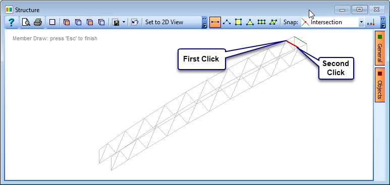
- Draw the two end vertical members using the single member draw mode toolbar icon
 by clicking on the bottom intersection then the top.
 - The diagonal bracing can now be drawn as multiple members, zigzagging from bottom to top across the truss.
-
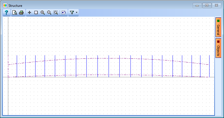
The members of the truss can be seen more clearly in the graphics if the construction lines and Setting out objects are turned off using the Objects button on the right of the graphics screen.
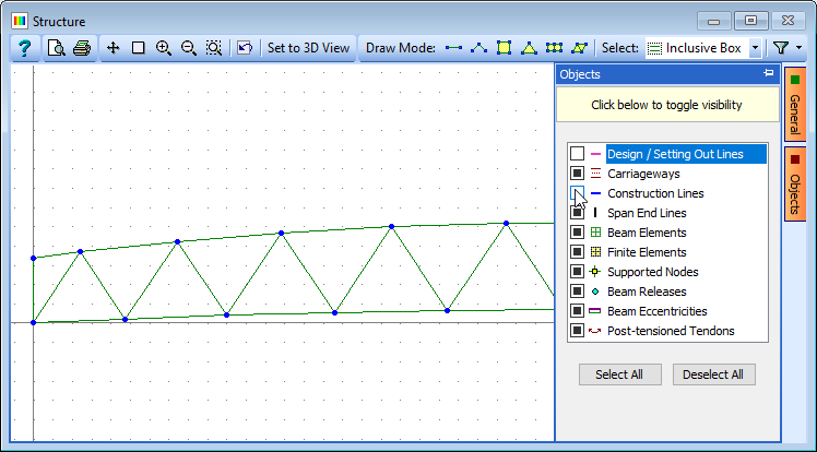
-
Close the Define Sub Model Members form with the ✓ OK button.
- Copy this complete sub-model to the second side and rename the second sub model "Truss 2". This is done by right clicking on the first sub model entry in the navigation window and selecting the Copy option.
-
In the Copy Sub Model form click on the Define button to define a new origin and plane for the copied sub model.
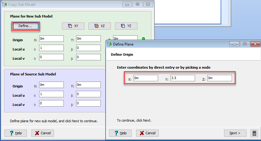
-
Set the origin to (0.0, 3.5, 0.0) then click on the Next > button.
- The orientation of the plane does not need changing for the new sub-model so click on "Next" on the next two forms then ✓ OK to confirm.
- To actually create the new set of members click on the Next > button on the Copy Sub Model form and then ✓ OK to confirm.
- Rename this new Sub model to "Truss 2" in the same way as the first.
- To view the two trusses in isometric click on the Structure item in the navigation window and use the appropriate
 toolbar button if necessary.
 - Add a new 3D sub-model to the Structure in the navigation window and in the graphics screen set the Draw Mode to single member .
-
Draw the top boom transverse connecting members one by one by clicking on the node points in the graphics screen. The structure may need rotating into a suitable orientation to achieve this. Panning and zooming options in the toolbar may also benefit node selection.
-
Add the top diagonal bracing in the same way but use the multiple beam members option
, finishing with the "Esc" key when the last member has been drawn. - Close the Define Sub Model Members form with the ✓ OK button.
- Rename the 3D sub Model to "Top Bracing".
- Add an additional 3D sub-model and repeat the exercise in 30 to 33 above but name it "Bottom Bracing & Deck". The graphics orientation and zoom will need adjusting to achieve this. Note the different layout between the top and bottom bracing.
- In the navigation window use to add Supported Nodes to the Structure (as opposed to the sub models).
- Change the view direction to Isometric using the graphics toolbar button.
- Also in the toolbar change the Along Span End dropdown field to "All Joints."
- In the graphics window click on the two nodes at the near end of the bottom boom members. This will add small square support icons at these locations and add two entries into the supports table.
- Repeat this for the two nodes at the other end of the bottom boom members.
- In the Define Support Nodes form set the Group Type: to Variable and then change the X Direct Restraint to Free for the second two nodes.
-
Close the Define Supported Nodes form using the ✓ OK button.
Section Properties
-
Change the navigation window to Design Sections.
The sections for all but the deck bracing have already been created in section files, so these can be imported. The deck bracing is defined by a parametric shape.
-
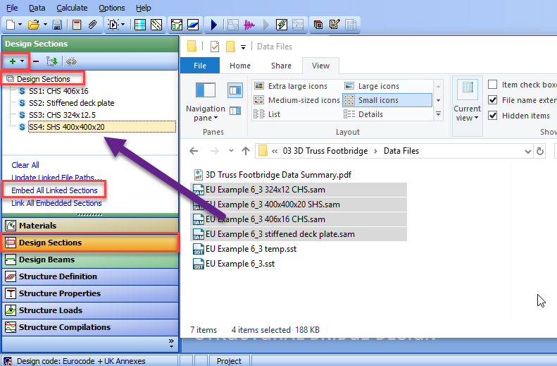
Open up a standard file browser (outside of ASBD) and navigate to where the section data files are located. There should be four section files, namely:
- EU Example 6_3 324x12 CHS.sam
- EU Example 6_3 400x400x20 SHS.sam
- EU Example 6_3 406x16 CHS.sam
- EU Example 6_3 Stiffened Deck Plate.sam
-
Select all these files together (using the Ctrl key whilst clicking on them) and drag them using the left mouse button into the white space of the Design Sections navigation window.
-
The data from these linked files can be embedded into the project by clicking on the navigation window task of Embed All Linked Sections. The navigation tree can be tidied up by right mouse clicking in the navigation window and selecting "Collapse All."
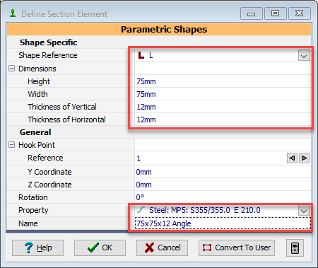
- The last section to be defined is an "L" parametric shape for the deck bracing. Click on the button at the top of the navigation window and select the Parametric Shape option from the list.
- In the Define Section Element form set Shape Reference to "L", height: and width: to "75mm", thickness of horizontal and thickness of vertical to "12mm".
-
Also change the Name to "75x75x12 Angle" and Property to the S355/355 structural steel before using ✓ OK to close the window.
-
Rename this new section (using the right mouse button context menu) to "Deck Plate Bracing."
- We now need to assign the various sections to the beam members in the structure so change the navigation window to Structure Properties and click on the task Create Section and Beam Groups, which should create 5 structure properties to assign.
-
Click on the 400x400x20 SHS item in the navigation window to open the data form Structure Properties: Section. This section needs to be assigned to the bottom boom members of the two trusses.
This could be done by clicking on each bottom boom member individually in the graphics window but we will use filtering and orientation to make this a little simpler.
-
To filter the structure to just the two trusses, click on the filter button in the graphics toolbar
 . Because the toolbar is shortened due to the combined display with the section this may be hidden so the small triangle at the end of the toolbar must be clicked to display it.
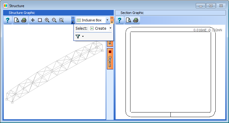
-
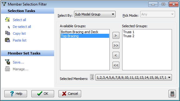
In the Member Selection Filter form click on the De-select all item in the Selection Tasks.
- Then change Select By: to "Sub Model Group."
-
Double click on Truss 1 and Truss 2 to move them to the Selected Groups: as shown before closing the form with the ✓ OK button.
-
Change the view of the structure, to view it from the South, by using the graphics toolbar button
 .
. -
Window round the bottom boom members as shown to assign this section to the selected members in both trusses (ensure that the graphics dropdown is set to "Inclusive Box").
-
Close the data form for this section with the ✓ OK button then open the Section Data form for 406x16 CHS. This can be assigned to the top boom members in the same way as 49 above.
- To assign the properties for the other beams we first remove the filter by clicking on the small arrow next to the filter icon and choosing "Select All" from the list.
-
Open the Section Data form for the section 324x12 CHS. Change "Inclusive Box" to "Exclusive box" in the graphics toolbar and then window round the top boom of the structure. This is in effect a crossing box (dotted) that will select all members wholly within the box and any member that is crossed by it.

-
It will try to overwrite the top boom members already defined but a confirmation box allow this not to happen by selecting the No to All button.
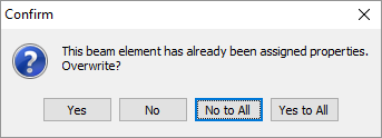
-
It may appear in the graphics that the top boom members have been selected (turned red) but in fact it is the bracing which is shown. This can be confirmed by changing the view to an isometric view. Click on the ✓ OK button in the Structure Properties: Section form to close it.
- The Stiffened deck plate property and the 75x75x12 angle bracing can be assigned in a similar way. This is done by first filtering the structure to the Bottom Bracing & deck sub model, in a similar way as described in Error! Reference source not found.
- Then assign the property, member by member, by clicking on them individually in the graphics screen.
- Assign 75x75x12 angle properties to the diagonal bracing members in the bottom deck.
-
Assign the stiffened Deck Plate properties to other members in the bottom deck.
Section Properties
-
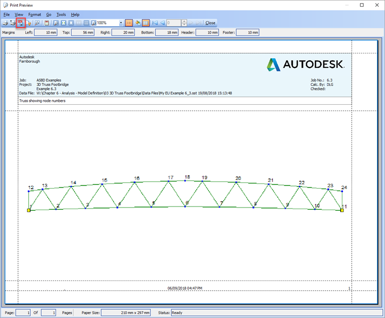
The structure is now completely defined. It is required to produce two graphical reports to show the node numbering of Truss 1 and Truss 2.
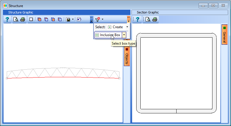
- With all data forms closed and just the graphics window visible, filter the model to just "Truss 1". This can be done by using the drop down selection displayed when the small arrow at the right of the filter button is clicked.
-
Click on the General button on the right of the graphics window and tick the boxes for Annotate Joints, Show Nodes and Filtered Members Only. The display can be viewed as a "Print preview" before printing a hard copy. This is done by clicking on the print preview icon on the graphics toolbar. Also, a PDF of the graphic window can be generated by clicking on the PDF icon at the top of the print preview window.
-
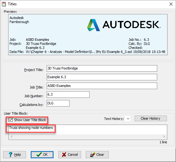
You can see that there is nothing on the preview to say what part of the structure we are looking at. User titles can be added at this stage to highlight this. Click on the preview menu item Format | Titles and tick the box for Show User Title Block. A title of "Truss 1 showing node numbers" can then be added in the text field before closing the Titles form with the ✓ OK button. The new title can now be seen added to the graphics.
-
Print a hard copy, if required, using the File | Print menu item then close the Print Preview window using File | Close.
- Repeat steps 76 to 78 with the filter and titles set for Truss 2.
- Remove the filter on the structure, switch off joint annotation, remove the user title block and set the viewing direction in the graphics to isometric.
- Now create a data summary and save as a PDF file using the menu item File | Data Reports...
- Click on the "Include All" button and then the "View" button.
- In the Results Viewer form click on the PDF View tab at the bottom of the window to display the results in PDF format. Note that you can navigate to different sections of the report using the hyperlinks displayed on the first page.
-
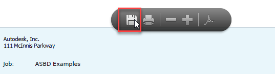
To save this as a file click on the save icon in the floating toolbar and enter a name of "3D Truss Footbridge Data Summary.PDF" before closing the Results Viewer and the Data Reports form.
-
Finally save the data file using the menu item File | Save as... using a file name of "My EU Example 6_3.sst".
- Close the program.
Summary
This example highlights the methods used to create a general 3D structure by building up sub-models. It introduces curved setting out objects, and multiple construction lines to define the geometry of each truss. Particular interest is paid to filtering of the structure to simplify certain procedures.
Source: https://knowledge.autodesk.com/support/structural-bridge-design/learn-explore/caas/CloudHelp/cloudhelp/ENU/ASBD-ModelDefinition/files/ASBD-ModelDefinition-3DTrussFootbridge-html-html.html
0 Response to "How to Draw Truss in Autocad"
Post a Comment